Rockford Industrial Area Revival Project - Moderated newsgroup > Motor Drives and Controls
> Rockford
> West
> Watson marlow 624U auto control IP55 pump
Watson marlow 624U auto control IP55 pump
Watson marlow 624U auto control IP55 pump
From: Carissa Cain
Subject Watson marlow 624U auto control IP55 pump
NEW ITEM W/O ORIGINAL BOX!!!!!!!!!! 1 YEAR WARRANTY MRO
When this pump unit is used as a stand-alone pump it complies with: Machinery Directive 98/37/EC EN60204-1, Low Voltage Directive 73/23/EEC EN61010-1, EMC Directive 89/336/EEC, EN50081-1/EN50082-1.
In the interests of safety, this pump and the tubing selected should only be used by competent, suitably trained personnel after they have read and understood this manual, and considered any hazard involved.
Any person who is involved in the installation or maintenance of this equipment should be fully competent to carry out the work. In the UK this person should also be familiar with the Health and Safety at Work Act 1974.
This symbol, used on the pump and in this manual, means: Caution, risk of electric shock.
This symbol, used on the pump and in this manual, means: Caution, refer to accompanying documents.
This symbol, used on the pump and in this manual, means: Do not allow fingers to contact moving parts.
There are dangerous voltages (at mains potential) inside the pump. If access is required, isolate the pump from the mains before removing the cover.
Recommended operating procedures
DO keep delivery and suction lines as short as possible using a minimum number of swept bends.
DO use suction and delivery pipelines with a bore equal to or larger than the bore of the tube fitted in the pumphead. When pumping viscous fluids, the losses caused by increased friction can be overcome by using pipe runs with a cross sectional area several times greater than the pumping element.
DO fit an extra length of pump tube in the system to enable tube transfer. This will extend tube life and minimise the downtime of the pumping circuit.
DO keep the track and rollers clean.
The self-priming nature of peristaltic pumps means valves are not required. Any valves fitted must cause no restriction to flow in the pumping circuit.
When using Marprene tubing, after the first 30 minutes of running, re-tension the tube in the pumphead. Open the guard, hold the tubing at one port whilst pulling the tube tight through the second port. This is to counteract the normal stretching that occurs with Marprene which can go unnoticed and result in poor tube life.
Tube selection The chemical compatibility list published in the Watson-Marlow catalogue is only a guide. If in doubt about the compatibility of a tube material and the duty fluid, request a tube sample card for immersion trials.
The 624U is suitable for single phase mains electricity supplies only.
To ensure correct lubrication of the gearbox the pump should only be run while its feet are on a horizontal surface. The pump should be positioned to allow a free flow of air around it.
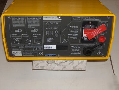
* Remove the small transparent plate on the rear panel to gain access to the voltage selector and terminal block.
* Set the voltage selector to either 120V for 100-120V 50/60Hz single phase AC supplies or 240V for 220-240V 50/60Hz single phase AC supplies.
* Route the mains supply cable through the entry point to the right of the recess, and couple the cable to the terminal block as shown on the rear panel.
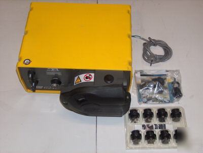
* There are two alternative connectors. One accepts 20mm rigid or flexible conduit, and the other accepts three core 0.75 square millimetre PVC sheathed mains cable (via the screwed adapter supplied) so that a mains lead can be used.
* Ensure that the mains lead is securely retained in the strain relief gland so that IP55 ingress protection is maintained.
* Securely replace the transparent plate and the gasket over the recess.
1. Armoured cable strain relief gland GR 0018
3. Strain relief gland SL0020
Ingress protection standard will be compromised if the transparent plate is not replaced.
The pump rear panel recess houses the following:
1. Signal range potentiometer
6. Signal offset potentiometer
Should the pump fail to operate, make the following checks to determine whether or not servicing is required.
* Check that the power switch is on.
* Check the mains supply is available at the pump.
* Check the voltage selector switch is in the correct position.
* Check the fuse in the mains socket.
* Check that the pump is not stalled by incorrect fitting of tubing.
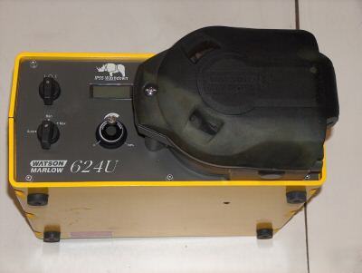
Set the Auto/Manual/Max switch to Manual.
* Start up Direction Start the pump by turning the Forward/Off/Reverse switch to the required direction of rotation. The preferred direction of rotation is clockwise (with fluid entering at the bottom of the pumphead), which will ensure the longest possible tube life. To operate against higher pressures use anticlockwise rotation.
* Prime To prime the pump at maximum speed press the Max button.
* Speed control Set speed is indicated on the digital display.
* Stop Stop the pump by turning the Forward/Off/Reverse switch to its central Off position. To change the direction of flow, turn the Forward/Off/Reverse switch to its central Off position until the pumphead rotor stops, and then turn it to the required direction of rotation.
If returning from auto control to manual control, it is not necessary to disconnect the process signal from the pump or adjust the calibration potentiometers.
* Set the Auto/Manual/Max switch to Auto.
For all auto and remote control operations, the drive is supplied with a 6-pin waterproof connector.
Watson-Marlow part number UP0035
Correct assembly of the connector plug is essential or the ingress protection standard will be compromised. Never apply mains voltage across any pins on the 6-pin socket. Up to 30V may be applied across pins 2 and 3 but not across other pins. Permanent damage not covered by warranty may result in both instances.
The pump is controllable by an analogue process signal of up to 30V or 32mA. The pump will provide an increasing flow rate for rising control signal (non-inverted response) or an increasing flow rate for falling control signal (inverted response).
* Signal offset is the process signal level which has to be reached in order for the pump rotor to start rotating.
* Signal range is the change in process signal level necessary to produce the required change in pump rotor speed.
For example, when using a 4mA to 20mA process signal:
For voltage modes, a stable variable DC voltage source can be used in conjunction with a DC voltmeter, (maximum 30V DC). Polarity set for a non-inverted response. Reverse polarity for an inverted response.
For current modes, the same DC source can be used in conjunction with a DC milliampere meter, (maximum 32mA). Polarity set for a non-inverted response. Reverse polarity for an inverted response.
Ensure the correct wiring of the 6 pin plug and insert the plug into the socket at the rear of the pump.
* Remove the rear panel window.
* Turn the signal offset potentiometer clockwise until the slider traverse limit is reached and is signified by a clicking noise. Now turn the potentiometer ten turns anticlockwise. Repeat for the signal range potentiometer. This ensures correct potentiometer set-up for calibration.
* Set the process signal offset.
* Turn the signal offset potentiometer clockwise to set the drive shaft speed to the desired minimum.
* Set the process signal at its upper range limit (not exceeding 30V or 32mA).
* Turn the signal range potentiometer clockwise to set the drive shaft speed to the desired maximum.
* Repeat the procedure until pump response coincides exactly with the process signal.
* If the signal rises above its designated maximum, the action of the signal conditioner will be to hold the motor to maximum speed at the MAX setting indicated by the LED indicator flashing. If the signal rises above 30V, permanent damage, not covered by warranty, may result.
Securely replace the rear panel recess cover on the back of the pump ensuring the gasket is in the correct position. This will avoid the ingress protection standard of the pump being compromised.
Connect remote switch between pins 2 and 5 of the 6 pin socket. Close contact to stop the pump, open to run.
A remote potentiometer with a nominal value of between 4.7kohm and 5kohm should be wired as shown, When using a remote potentiometer do not connect a voltage/current control signal at the same time. The speed control signal will require calibration relative to the minimum and maximum settings of the potentiometer. Use the offset and range potentiometers as described under calibration.
This facility can be used to indicate motor speed or total the number of motor revolutions. Select either 1) 0-5V DC or 2) 5V pulse train output using the tachometer output switch.
The only scheduled maintenance required for the 624U/R is inspection of the motor brushes and their replacement before their length is less than 6mm. The life of the brushes will depend on the duty of the pump, but is expected to be a minimum of 4,000 hours at maximum speed.
If the pump requires cleaning, use a mild solution of detergent in water after removing the pumphead. Do not use strong solvents.
For gearbox rebuilds, use Lubriplate GR-132 (Bodine reference LG-23) only. This is a lithium combination type thickener, NL GI No.1 grade, non-corrosive extreme pressure lubricant. This product is water resistant and resistant to a large degree to most other contaminants.
Machinery directive 98/37/EC EN60204-1
Low voltage directive 73/23/EEC EN61010-1
EMC directive 89/336/EEC EN50081-1/EN50082-1
Specific drive performance details such as loaded drive speed variation against mains supply voltage fluctuation and drive stability from a cold start to normal operating temperature are available on request. For further information please contact Watson-Marlow Technical Support Department.
FOR ANY QUESTION CONTACT ME A CCain@rockford-industrial.com
Contact: CCain@rockford-industrial.com (Carissa Cain)