Rockford Industrial Area Revival Project - Moderated newsgroup > Motor Drives and Controls
> Rockford
> West
> Thorlabs DET110 high speed detector 350 to 1100NM
Thorlabs DET110 high speed detector 350 to 1100NM
Thorlabs DET110 high speed detector 350 to 1100NM
From: Jeri Smith
Subject Thorlabs DET110 high speed detector 350 to 1100NM
DET110 - HIGH-SPEED SILICON DETECTOR
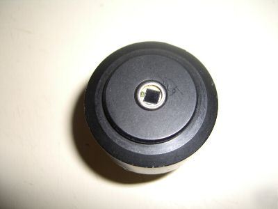
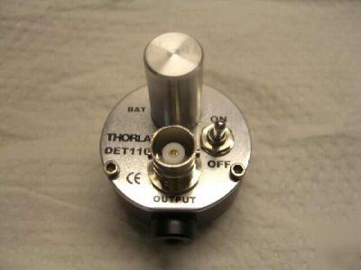
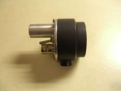
Thorlabs’ DET110 is a ready-to-use high-speed photo detector. The unit comes complete with a photodiode and internal 12V bias battery enclosed in a ruggedized aluminum housing. The head includes a removable 1†optical coupler (SM1T1), providing easy mounting of ND filters; spectral filters and other Thorlabs 1†stackable lens mount accessories. Also available are fiber adapters (SMA, FC and ST style). An #8-32 tapped hole is provided on the base of the housing to mount the detector directly to a Thorlabs’ positioning device (1/2†post holder, mounting plates, etc.).
Detector: Silicon PIN Housing: Black Anodized Aluminum
Spectral Response: 350-1100nm Size: ö1.43†x 1.67â€
Peak Wavelength: 960nm+/-50nm Output: BNC, DC-Coupled
Rise/Fall Time1: 20ns Bias: 12V Battery (Type A23)
Diode Capacitance: 20pF Mounting: 8-32 (M4) Tapped Hole
NEP: 1.2 x 10⁻¹⁴W/ HZ Diode Socket: TO-5, Anode Marked
Active Area: 13mm2 0.5 J/cm2 (10ns pulse) 3.6mm x 3.6mm square
Thorlabs DET series are ideal for measuring both pulsed and CW light sources. The DET110 includes a reversed-biased PIN photo diode, bias battery, and ON/OFF switch packaged in a ruggedized housing. The BNC output signal is the direct photocurrent out of the photo diode anode and is a function of the incident light power and wavelength. The Spectral
Responsivity, R(ë), can be obtained from Figure 2 to estimate the amount of photocurrent to expect. Most users will wish to convert this photocurrent to a voltage for viewing on an oscilloscope or DVM. This is accomplished by adding an external load resistance, RLOAD. The output voltage is derived as:
The bandwidth, fBW, and the rise-time response, tR, are determined from the diode capacitance, CJ, and the load resistance, RLOAD as shown below:
fBW = 1 / (2 * ð * RLOAD * CJ)
For maximum bandwidth, we recommend using a 50. coax cable with a 50. terminating resistor at the end of the coax. This will also minimize ringing by matching the coax with its characteristic impedance. If bandwidth is not important, you may increase the amount of voltage for a given input light by increasing the RLOAD up to a maximum of 10K.
Note: The detector has an AC path to ground even with the switch in the OFF position. It is normal to see an output response to an AC signal with the switch in this state. However, because the detector is unbiased, operation in this mode is not recommended.
Additional units will be available in a few weeks. Contact us for additional information.
Contact: J-smith@rockford-industrial.com (Jeri Smith)